Our expert responds #27

12
gennaio
2021
Hydraulic coating - an example
QUESTION
Is it possible to have an example of the effects of the lack of hydraulic coating, as understood by chap. 9.3 Accumulation tanks of UNI EN 12845:2020?
ANSWER
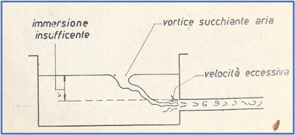
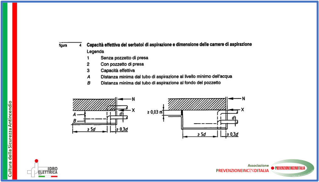
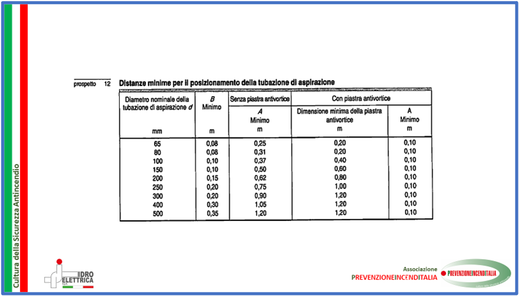
Chap. 9.3 Accumulation tanks of UNI EN 12845:2020 and in particular point 9.3.5 (FIGURE 4 and TABLE 12), seeks to dictate the conditions so that the dragging of air from the free water of the tank does not occur, due to the turbulence generated by too high of local speeds.
This phenomenon has already been taken into account in the questions:
- # 11 Submergence of the Vertical Turbine Pumps (VTP)
- # 25 Difference between geometric volume and useful volume of the fire-fighting water supply storage
Here a practical case will be shown, in which the failure to comply with the minimum hydraulic coating, has led to an immediate decrease in the performance of the pump in question and a rapid deterioration of the impeller.
In the image, a sequence is shown that illustrates the emptying of the storage tank, from which the pump is sucking in POSITIVE HEAD mode.
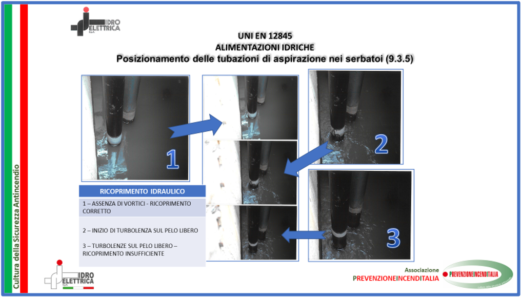
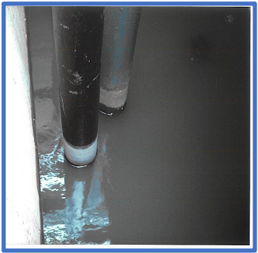
The initial level of free water is clearly indicated by the top of the white trace present on the pipe. Up to the level reached in FIGURE 1, there is no development of surface vortices.
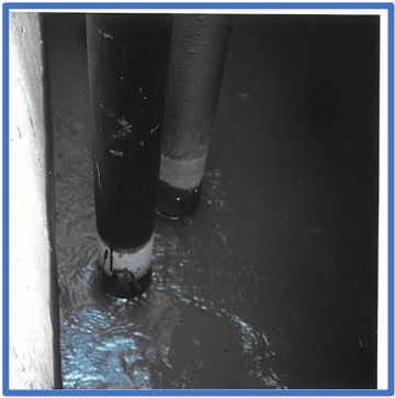
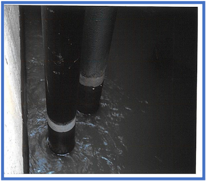
FIGURE 1
FIGURE 2
FIGURE 3
When the free water reaches the level that can be seen in FIGURE 2, then the vortices due to the increase in speed begin to be present around the pipe. This is how the dragging of the air inside the pipe begins. Air that will obviously reach the suction mouth of the pump.
By lowering the free water to the level shown in FIGURE 3, one has a complete development of the vortices and a massive inlet of air inside the intake duct.
Since, in this case, the duct is SUCTION LIFT, there is also the occurrence of the concomitant phenomenon of cavitation. In fact, the pressure inside the duct becomes lower than the vapour pressure of the water and therefore, a part of the liquid evaporates at room temperature.
Within the duct there is therefore the presence of:
- a two-phase fluid formed by liquid water and gas water, formed due to excessive depression within the intake pipe (pressure < vapour pressure)
- of air coming directly from the atmosphere, due to the excessive speed of entry into the intake duct; this drag is caused by poor coating
These two phenomena, which as we have said, are completely separate, give rise, alone or together, to a deterioration in the performance of the pump (an example of the curve trend is shown in FIGURE 4).
Therefore, the possibility of obtaining the Q/H point provided for by the design calculations is lost.
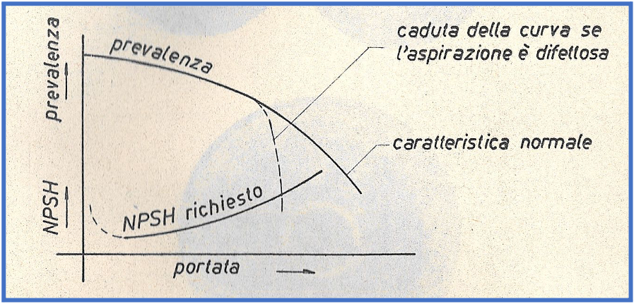
FIGURE 4
Furthermore, the continuation of the described conditions will lead to the rapid destruction of the machine. In particular, it will cause damage to the impeller and supports. Damage related both to the implosion of cavitation bubbles and to the presence of unbalanced axial thrusts, which cause displacements of the impeller and stresses on the bearings and their workplaces.
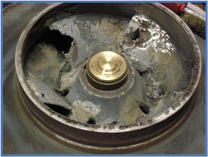
FIGURE 5
To avoid the occurrence of these problems, it is therefore necessary to refer to UNI EN 12845:2020 and respect the content of:
- chap. 9.3 Accumulation tanks and in particular point 9.3.5, Figure 4 and Table 12; where there are indications for avoiding the occurrence of surface vortices
- chap. 10.6 Suction conditions and in particular point 10.6.2.1. where it is imposed that NPSHd > NPSHr + 1 at the maximum flow rate provided for the pump
12
gennaio
2021
8
marzo
2021
23
marzo
2021
20
aprile
2021
27
maggio
2021
28
giugno
2021
29
giugno
2021
3
settembre
2021
1
ottobre
2021
23
novembre
2021